ESP32-C3 XIAO LED Fade Glow Control Using a Potentiometer in Wokwi
Summary: This guide demonstrates how to simulate the compact Seeed Studio XIAO ESP32-C3 microcontroller on Wokwi to dynamically control LED brightness using an analog potentiometer. Learn how to map potentiometer analog inputs to PWM output duty cycles for smooth dimming and glowing effects.
Key Takeaways
- Hardware Simulation via Wokwi: Test and debug ESP32-C3 circuits virtually online without needing physical microcontrollers or components.
- Analog Input Processing: Utilize the ESP32-C3's Analog-to-Digital Converter (ADC) to read variable resistance values from a potentiometer.
- Pulse Width Modulation (PWM): Map raw analog sensor data to PWM signals to dynamically control LED brightness levels.
Detailed Overview
The Seeed Studio XIAO ESP32-C3 is an ultra-small development board powered by the RISC-V ESP32-C3 SoC, offering low-power performance alongside built-in Wi-Fi and Bluetooth capabilities. In micro-controller projects, learning how to interface analog inputs with variable outputs is a fundamental skill.
In this demonstration, a potentiometer acts as a manual analog input control that modulates the power delivered to an LED, creating a smooth fading and glowing visual effect. The entire circuit design and code execution are handled through the browser-based Wokwi simulation platform.
Core Components & Mechanics
- ESP32-C3 XIAO Board: Serves as the central processing unit running the micro-controller logic.
- Potentiometer: Functions as a variable voltage divider. Turning the dial alters the output voltage sent to the board's analog input pin.
- LED & Resistor: Receives a Pulse Width Modulation (PWM) signal from the board. The varying duty cycle adjusts the effective voltage across the LED, driving the dimming and glowing behavior.
Deep Dive & Technical Insights
Simulating embedded circuits using tools like Wokwi helps streamline code testing, prevent accidental hardware damage, and accelerate hardware prototyping.
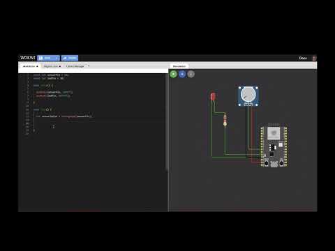
Hardware Connections Breakdown
- Potentiometer VCC Pin: Connected to 3.3 V power output on the ESP32-C3.
- Potentiometer GND Pin: Connected to Common Ground (GND).
- Potentiometer Wiper (Signal) Pin: Connected to an ADC pin on the ESP32-C3 XIAO board.
- LED Anode (Positive Pin): Connected through a resistor to a PWM-capable GPIO output pin.
- LED Cathode (Negative Pin): Connected to Common Ground (GND).

Logic Implementation (ADC to PWM)
Whether implemented in MicroPython or CircuitPython/C++, the process follows a simple execution loop:
- Initialization: Set up the target ADC pin to read voltage signals from the potentiometer wiper and configure the LED pin for PWM output.
- Analog Read: Continuously poll the ADC pin to obtain raw digital representation values corresponding to potentiometer position.
- Range Scaling: Map the incoming ADC value (typically 12-bit range, 0-4095) to the appropriate PWM duty cycle resolution.
- PWM Update: Write the mapped duty cycle to the LED output pin, causing the LED to smoothly fade down or glow brighter as the knob turns.
Conclusion & Resources
Using browser-based development environments like Wokwi simplifies testing interactive electronics projects. Combining analog inputs from potentiometers with PWM outputs provides a solid foundation for building dimmers, speed controllers, and interactive user interfaces with the ESP32-C3 XIAO.
Resources
- Explore the project simulation directly on Wokwi: https://wokwi.com/projects/3857328008...