Electromagnetically Controlled RADAR Sensor for Interactive Light Object for LightOnLabs 2026
Summary: This article outlines the development of an electromagnetically controlled RADAR-driven LED controller designed for interactive light installations. By pairing an ESP32-C3 microchip with an HLK-LD2410C mmWave sensor, the system accurately detects human presence and distance through solid glass structures to drive expressive, fluid illumination transitions.
Key Takeaways
- Point 1: High-frequency microwave radar sensors (like the LD2410C) reliably penetrate physical obstacles like glass, bypassing the limitations of optical and ultrasonic sensor alternatives.
- Point 2: Combining hardware-driven PWM filtering with software-based low-pass filtering stabilizes highly volatile sensor measurements to produce smooth, non-flickering light behaviors.
- Point 3: Scaling art installations to multi-device configurations requires early testing for electromagnetic interference, especially when operating multiple high-frequency radar components in closed environments.
Detailed Overview
Background and Context
The project was initiated for artist Ster Borgman, whose work explores natural processes and the transformative properties of materials. Ster’s artwork mimics chemical processes—melting sand into glass and dripping rust formations—to foster appreciation for non-human nature. For the LightOnLabs 2026 showcase, the artist envisioned an interactive landscape consisting of several wall-mounted, glowing installations.


The Artistic & Technical Brief
The goal is to design a robust, custom LED driver capable of interacting dynamically with spectators. The light intensity must correspond directly with user proximity:
- At a distance of 1.5 to 2.5 meters, the object begins a slow, warm fade-in.
- Within 30 centimeters, the object achieves maximum brightness.
- When multiple objects are grouped in a single room, they together form a responsive, breathing landscape of light.


Overcoming the Sensory Barrier
Standard human detection methods present major structural flaws:
- Optical Sensors (PIR/IR) fail because glass panels bend and block light rays.
- Ultrasonic Sensors fail as sound waves echo off glass surfaces instead of passing through them.
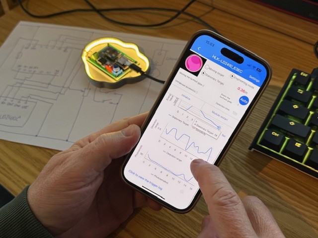
Electromagnetic microwave technology provides the ideal solution. Operating on the 24 GHz band, the Hi-Link LD2410C mmWave radar sensor can easily peer through thin, protective housings (such as organic or inorganic glass panels) while remaining completely hidden from the user's view.


Multi-Device Interference Concerns
Installing roughly ten radar-equipped modules onto a single wall structure presents a major challenge: electromagnetic cross-talk. To prevent modules from triggering each other, the development roadmap includes physical spacing tests and sensory isolation assessments using two preliminary working prototypes before mass assembly.
Deep Dive & Technical Insights
System Hardware Architecture
Driving high-density COB (Chip-on-Board) LED strips requires high-current power handling. A standard microcontroller I/O pin cannot provide the current necessary to light a long strip without destroying the silicon. The design bypasses this restriction by using a dedicated logic-level MOSFET configuration to safely modulate high-current loads at high frequencies.
| Component Class | Selected Part | Function |
|---|---|---|
| Brain / Processing | Seeed Studio XIAO ESP32-C3 | Reads UART sensor packets; processes smoothing algorithms; generates PWM output. |
| Radar Unit | Hi-Link LD2410C | 24 GHz mmWave presence & range sensor with a configurable UART interface. |
| Power Switch | IRLZ44N N-Channel MOSFET | Logic-level, high-capacity MOSFET capable of handling up to 55 V/47 A load. |
| Gate Driver | 2N7000 FET | Translates ESP32's lower 3.3 V logic level to robust gate voltage signals. |
| Light Source | COB LED Strip (5 V, 3000K) | Pixel-free, continuous hot-spot-free light strip mimicking incandescent embers. |
| Cabling & Power | NFHK 90° USB-C Cable | Compact, tight-radius connection for slim, wall-mounted frames. |


Logic and Signal Processing
Radar data is fundamentally chaotic, containing rapid micro-fluctuations (spikes) caused by air movements, dust, or fast-moving targets. To create a natural-looking breathing effect, raw UART distance values must pass through a programmatic filter cascade:
- Spike Filtering: Discards extreme single-frame sensor fluctuations.
- Hold-State Retention: Holds the active presence state momentarily during brief sensor dropouts.
- Software Low-Pass Filter: Features an engineered ~0.5-second lag. This smoothly averages out distance transitions to construct a gentle and deliberate illumination curve.
[LD2410C Sensor] ---> (UART Stream) ---> [XIAO ESP32-C3]
                                                │
                                       (Spike & Low-pass Filter)
                                                │
                                                ▼
[COB LED Strip] <--- (PWM Signal) <--- [MOSFET Gate Driver Stage]
Prototyping Stages
- Phase 1: Construct a functional prototype focusing purely on presence detection with adjustable fade-up/fade-down cycles to test inter-device interference.
- Phase 2: Incorporate dynamic range filtering so that the relative physical distance actively scales the PWM output level in real-time.


Conclusion & Resources
Summary
The intersection of custom embedded computing, analog sensory circuits, and modern art projects creates exciting technical opportunities. By pairing a 24 GHz mmWave radar module with logic-level power MOSFETs and an ESP32-C3, this prototype delivers smooth, touchless human interactions that function seamlessly behind solid glass barriers.
- For video demonstrations of the initial prototype's lighting cycle: Watch the Prototype Video
- Learn more about the underlying physical glass artwork at Ster Borgman's Official Website