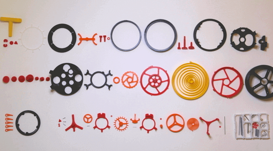
Let’s get one thing straight: 3D printing a mechanical clock is hard. 3D printing a working tourbillon—a mechanism invented over 200 years ago by Abraham-Louis Breguet to negate the effects of gravity on an escapement—is bordering on masochism. Yet, Swiss software engineer Christoph Laimer did exactly that, earning him Pinshape’s Designer of the Month.
If you spend any time slicing STLs or tuning your extrusion multipliers, you know that FDM printers fight you on tight tolerances. Laimer bypassed traditional metal milling entirely to build this mechanism using standard consumer-grade plastics. Let’s dig into the CAD architecture, slicing parameters, and assembly logic that made it tick.
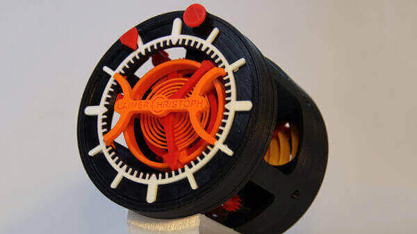 Swiss engineer Christoph Laimer.
Not Your Average Slicing Job
When prototyping a multi-part mechanical system, the initial challenge isn’t the design—it’s accounting for thermal expansion, elephant’s foot, and the layer inconsistencies inherent to fused deposition modeling (FDM).
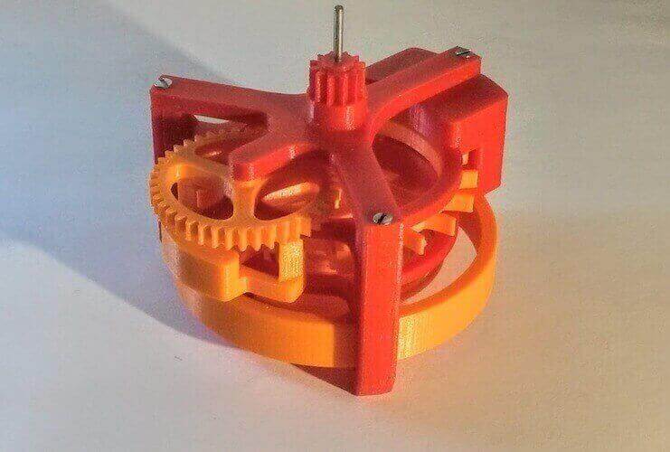
Laimer modeled the entire clock in Autodesk Fusion 360, iterating heavily to guarantee that the final escape wheel and pinion of the tourbillon could survive the physical forces of a tightly wound mainspring. Teeth snapping off gears is the primary failure mode in 3D printed horology, so he scaled the tourbillon to a pocket-watch/clock size rather than attempting a wrist-watch footprint.
Pro-Tip: If you are tackling gear trains in Fusion 360, don’t rely purely on theoretical pitch diameters. Print tolerance test gauges first to find your machine’s exact horizontal expansion offset.
The Magic Numbers: Print Settings
You can’t just hit “Slice” on a project containing 50+ interlocking mechanical parts. The tourbillon relies on variable layer heights based on the mechanical load and friction requirements of individual components.
| Component Group | Layer Height | Reasoning |
|---|---|---|
| Casing & Structural | 0.10 mm |
Standard resolution is sufficient for rigid parts, saving print time without sacrificing structural integrity. |
| Gears & Pinions | 0.10 mm |
Balances Z-axis strength with smooth tooth engagement. |
| Escapement & Anchor | 0.06 mm |
Critical for minimal friction. Any Z-banding here ruins the timing sequence. |
| Hairspring | 0.06 mm |
The most delicate piece. Requires ultimate precision to maintain consistent flexibility. |
The Elephant in the Room: The Printed Mainspring
Perhaps the wildest element of this build is the 2-meter long spiral mainspring made entirely out of plastic.
Printing a massive spiral spring flat on the bed introduces stringing issues that ruin the spring’s potential energy transfer. Laimer had to dig into his slicer’s advanced settings to solve this. If you are attempting this in Cura, pay close attention to your travel moves.
; Critical Slicer Adjustments for the Mainspring
[Travel_Settings]
Combing_Mode = Off
Avoid_Crossing_Perimeters = True
By toggling off the combing setting (or explicitly enabling Avoid Crossing Perimeters), you force the hotend to stay within the boundaries of the printed walls rather than taking shortcuts across the open gaps of the spiral. Without this adjustment, the nozzle oozes plastic across the spring coils, effectively fusing them together and destroying the part.
See It In Action
Laimer shared his entire assembly and explanation on YouTube. The video breaks down the co-axial escapement gear layout and shows the massive printed mainspring driving the entire assembly.
Watch the in-depth breakdown on YouTube
The Specs & Performance
Because we are dealing with plastic mechanics rather than ruby bearings and lubricated brass, the performance metrics look different from a Rolex:
- Power Reserve: ~30 minutes on a single full wind.
- Accuracy: Roughly 1 second of deviation per minute (highly dependent on the quality of your printed hairspring and final manual trimming).
- Part Count: Over 50 printed components, plus standard off-the-shelf screws, washers, and pins for the rotational axes.
Laimer’s own commentary perfectly sums up the intersection of software engineering and physical prototyping:
“I don’t actually have a background in watchmaking. Yes, I know I’m Swiss, and some people believe that Swiss children have that knowledge from birth. I instead learned about the function of a mechanical watch by studying various online articles. After having solved the gear ratio, the rest of the movement was relatively straightforward engineering work, though I totally underestimated the effort required to create a satisfying design.”
Why This Matters for Open Hardware
Projects like this prove that consumer 3D printers have moved beyond printing static desktop trinkets. By applying rigorous mechanical engineering principles to FDM technology, Laimer effectively democratized one of the most historically gatekept mechanisms in high-end horology. You don’t need a multi-axis CNC machine; you just need a well-calibrated setup, Fusion 360, and a ton of patience.
If you’ve got your extruder steps calibrated and your bed trammed flawlessly, I highly recommend downloading the STLs from Pinshape and taking a swing at printing this yourself. It will ruthlessly expose any mechanical flaws in your printer’s setup, and when you finally get that anchor ticking back and forth, it’s one of the most rewarding mechanical builds you can tackle.
Ready to test your printer’s limits? Grab the files from the open-source community, load up some premium filament, and start slicing.